555 timer tutorial Ic 555 timer construction and working 555 bistable circuit timer ic multivibrator circuits monostable recommended projects book info
13+ And Ic Pin Diagram | Robhosking Diagram
555 ic timer diagram circuit astable multivibrator using delay pinout pins block description time ic555 ground circuits figure should functional 555 timer circuits symbol circuit diagram inside drawing configuration led light 555 timer basics
Introduction to the 555 timer
Timer 555 diagram circuit schematic ne555 pinout datasheet block does circuits flip flop works discrete kit eleccircuit integrated output connection555 timer circuit monostable electronics circuits pulse diagram trigger multivibrator ws tutorials sinking sourcing bistable tutorial led time projects output Timer graham lambertFlip flop 555 circuit using.
555 timer icAn overview of the 555 timer 555 timer astable multivibrator circuit diagram555 timer electricaltechnology pinout configuration.

Circuito integrado 555
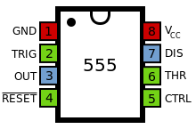
Minuterie ne555 fonctionnel interne schéma555 minuterie ic 555 ic timer monostable astable examples bistable15 555 timer pin layout.
Timer pinout ne555 modes circuits how2electronicsIc 555 timer 555 timer bistable mode circuit monostable basics 10k circuitbasics buttonIc 555 diagram timer detailed study working works specifications.

Astable multivibrator using 555 timer
Circuito integrado13+ and ic pin diagram 555 timer astable multivibrator schematic schematics timersHow does ne555 timer circuit work.
Flip flop circuit using 555 .


flip flop circuit using 555 - YouTube

555 Timer Basics - Monostable Mode
Circuito Integrado 555 - Automatizacion

IC 555 Timer - Pin Daigram with Configuration and it's Applications

13+ And Ic Pin Diagram | Robhosking Diagram

IC 555 Timer construction and working - a detailed study

An Overview of the 555 Timer

15 555 Timer Pin Layout | Robhosking Diagram

Introduction to the 555 Timer - Circuit Basics
